Propeller
Full

The

Airphibian Logo

home
Danbury
Continental
FAASpecs
Propeller
Versions
Photo Gallery
Garber
Video
Links


Frazer-
Silkscreens


Propeller attachment details -

The propeller had to be taken off and reattached easily and securely, thousands of times so that the car could operate and the plane could fly, and also in order to satisfy the FAA. I asked my father to write up how the propeller was changed and here is his response (April 20, 2009) -

The Franklin 150 hp aircraft engine has an 8" diameter flange on the front end of the crankshaft. That flange has eight 3/4" holes which normally are used to bolt the propeller onto the flanged end of the crankshaft. The bolts are normally already inserted through the propeller hub, and are aligned and matched through the crankshaft flange. Locknuts are applied on the backside of the crankshaft flange that lock the propeller hub in place.

The AIRPHIBIAN required the prop to be removed when used as an automobile requiring the design of a quick, safe, foolproof system for removal or the propeller.

Back and Front Plate Front Plate Full View
Front and Back Plate with threaded shaft about to be joined. Back of the Front Plate, showing the 8 protruding buttons that key into the Back plate and the 1.5" threaded shaft Attached propeller with prop crowling cone spinner attached (misaligned), which had a key to keep the spinner attached
A prop hub was designed that was permanently attached to the AIRPHIBIAN'S prop and permitted the quick, easy, safe attach and removal. It consisted of a matching prop flange backplate that perfectly matched the existing holes in the prop flange. It had attached 3/4" x 1/2" long snub nosed buttons which carried the engine torque into the propeller. The backplate was bolted to a frontplate by a threaded shaft which was so designed to act as a large diameter (approx 1.5") bolt. This inch and one half diameter bolt was threaded to match a female thread that was machined inside the crankshaft itself. Built in to this puller bolt was a 14" crank handle that would pull the propeller back flange securely against the engine flange, allowing a series of alignment holes to match another similiar series of holes allowing the two pins at the head of the crank, after firm tightening to be further pinned together preventing any loosening of the propellor to the engine. A bale was then pivoted up over the now inserted, locked crank and the prop cowling cone spinner was secured into the female housing on the bale, locked on, key in hand ready to start the engine.
 
Prop Full Team Rain 2nd
An early version of the hub with U-Bolts that held the prop to the flange plates The Spinner attached

Crankshaft/pullerbolt about to be inserted into crankshaft.

My Father said that the machinist that they used, Fred Underhill, put a lot of his own intellect into many of the innovations that were incorporated into the Airphibian and one of them was the Propeller Hub Mounting.

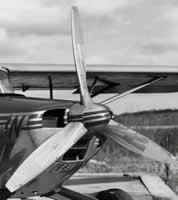
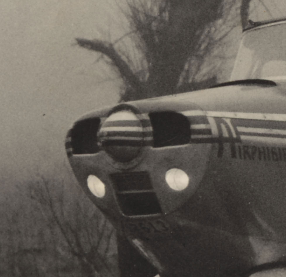
Interestingly enough, if you look at Fig 2 of the Patent, you'll see that the drawing is of a 2 bladed propeller, as are all the configurations in the patent itself. But all the photos show 3 bladed propellers.

A patent was granted for Hub Mounting for Propellers on Roadable Airplanes No. 2,509,096 on May 23, 1950. It was filed by R E Fulton Jr and Octavio J Alverez on June 23, 1945. It actually is a very well designed piece of machinery.

Prop Patent Fig 4

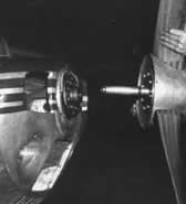
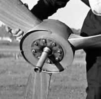
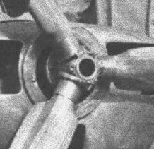
In this patent drawing the propeller is about to be attached to the back plate. The bolts that hold the prop to the front plate are the long bolts with the snub nosed buttons that engage in the holes in the back plate. The crank handle is ready to be turned to start the 1 1/2" Puller bolt to thread into the machined female thread in the engine crankshaft. The 2 pointed parts at the end of the crank handle engage in two holes at the end of the hub when the crank handle is pushed into its home inside the hollowed out engine crankshaft.


Patent Fig 15

Figures 15, 16, 17 and 18 show the overtorque prevention device built into the crankhandle. The crankhandle is actually made of layers of metal leaves that flex slightly as the handle is turned to tighten the puller bolt. There is a clip, #105, connected to one of the leaves attached to the handle of the crankhandle only. When the crankhandle is tightened enough the small returns on the 4th side of the clip will spread and move to the next leave, indicating that the bolt has been torqued enough. It is easily reset by pushing it back in place.

Prop Pat Fig3

In Fig 3 the propeller is ready to be used. Everything is attached, the crankhandle is in place and the spinner hub is locked on. The key to the spinner hub is also the ignition key


Home |  Danbury |  Continental |  FAASpecs |  Propeller |  Versions |  Photo Gallery |  Garber |  Video |  Links |  Frazer -Silkscreens


eXTReMe Tracker

This site was last updated January 11, 2015